


Plastic machining succeeds or fails long before the first tool touches the stock. Engineers, product designers, and buyers who understand how plastic behaves during cutting can reduce scrap, shorten setup time, and receive parts that fit and function as intended.
- Why Design Matters In Plastic Machining
- Choose The Material Before Finalizing Geometry
- Plan Tolerances Around Real Use
- Control Heat, Deflection, And Internal Stress
- Use Geometry That Supports Stable Cutting
- Build Better Tool Paths
- Support The Part During Machining
- Inspect Critical Features Clearly
- Avoid Common Design Mistakes
- Use A Pre-Production Checklist
- Final Takeaway
Unlike metal, plastic can flex under clamping pressure, retain internal stress, expand due to cutting heat, and change dimensions after machining. A CAD model may look straightforward, yet its wall thickness, pocket depth, clamping surfaces, and tolerance callouts can still make clean, repeatable production difficult.
Why Design Matters In Plastic Machining
Design for manufacturability is especially important when working with plastics because the material response is part of the process. Heat, elasticity, moisture exposure, chip evacuation, and residual stress all influence the finished size and surface quality. Designing around these variables provides the machinist with a more stable process and the customer with more predictable results.
Choose The Material Before Finalizing Geometry
Material choice should follow the part’s job, not simply price or availability. The broad family of thermoplastics includes materials with very different stiffness, friction, chemical resistance, impact strength, and moisture behavior.
Key Material Questions
- Will the part be exposed to heat, chemicals, moisture, sunlight, or repeated impacts?
- Does it need low friction, electrical insulation, transparency, or high stiffness?
- Will it carry a load, form a seal, accept threads, or support a press fit?
- Could moisture absorption, softness, or thermal movement affect its fit?
Acetal is often selected for low-friction, stable mechanical components. Nylon offers toughness but can absorb moisture. Polycarbonate provides impact resistance; acrylic offers clarity but is more brittle; ABS is useful for many general-purpose parts; and PTFE delivers excellent chemical resistance and low friction but can be challenging to hold tightly. Research on thermoplastic machinability also highlights the importance of heat, elasticity, thermal expansion, and cutting conditions when surface quality is critical.
Plan Tolerances Around Real Use
A tolerance is the allowed variation around a target dimension. It should reflect what the part must actually do. Tight controls are usually appropriate for mating holes, dowel locations, bearing seats, sliding surfaces, sealing faces, alignment points, and mounting patterns. Ordinary exterior faces often do not need the same precision.
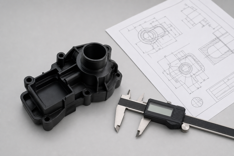
Applying tight tolerances everywhere increases inspection and machining effort without automatically improving performance. Plastic may also move after cutting as it cools, releases stress, or reaches a different moisture condition. Use general tolerances for noncritical features, then call out the dimensions that directly control fit, motion, sealing, or alignment.
Control Heat, Deflection, And Internal Stress
Heat is a major source of poor results. Dull tools, poor chip clearance, rubbing cuts, and overly aggressive paths can soften the material or leave a rough finish. Sharp tools suited to the chosen resin, effective chip removal, and cutting conditions that shear the material rather than repeatedly pressing against it are essential.
Leave controlled stock for roughing, then use a separate finishing pass. For example, a thin polycarbonate wall may measure correctly while clamped but shift slightly when released. That is why machine accuracy alone cannot guarantee part accuracy.
Use Geometry That Supports Stable Cutting
Wall Thickness, Corners, And Pockets
Avoid making walls thinner than the application requires. Thicker sections resist vibration, while ribs can add stiffness without making the entire part heavy. Internal corners should use the largest practical radius because rotating tools naturally leave rounded corners.
Deep, narrow pockets and slots require long, slender tools that can deflect or chatter. Review pocket depth, tool diameter, corner radius, and access together. Long tabs, tall fins, and raised walls also need support, reduced unsupported height, or a better machining orientation.
Build Better Tool Paths
- Rough steadily: Remove bulk material while leaving consistent finishing stock.
- Finish consistently: Use a final pass with controlled tool engagement.
- Smooth the motion: Limit abrupt direction changes that can create heat and chatter.
- Match tool and feature: Choose practical tool diameters for holes, slots, pockets, and contours.
- Plan the exit: Consider how the tool leaves an edge to reduce burrs and damage.
The fastest programmed feed rate is not always the fastest production method. A stable path that prevents rework, polishing, and rejected parts usually saves more time overall.
Support The Part During Machining
Plan how the part will be held during every setup. Broad, even clamping is preferable to concentrated force on flexible areas. Thin plates and large sheets often require support from below, while soft jaws, vacuum fixtures, or custom supports can prevent distortion. A part can be cut accurately and still fail inspection if the fixture changes its shape.
Inspect Critical Features Clearly
Start by confirming material and stock condition, then check overall length, width, thickness, datums, mounting features, holes, slots, and mating surfaces. Review flatness, parallelism, perpendicularity, surface finish, and visible edge quality afterward. For larger or highly stable parts, measure after the material has returned to a consistent temperature.
Avoid Common Design Mistakes
- Copying metal tolerances onto plastic drawings without review.
- Using sharp internal corners, thin walls, or deep pockets unnecessarily.
- Ignoring moisture conditioning, material grade, fillers, color, or finish requirements.
- Clamping flexible parts too tightly.
- Requesting a fine finish without allowing a finishing operation.
- Failing to identify which features are truly functional.
Use A Pre-Production Checklist
- State the exact material grade and identify critical dimensions and datums.
- Confirm that internal radii, walls, ribs, and tabs support standard tooling.
- Verify tool access, setup count, fixture support, and roughing and finishing allowance.
- Limit tight tolerances to functional features and simplify complex pockets where possible.
- Define an inspection method that matches the part’s real operating requirements.
Final Takeaway
Cleanly machined plastic parts begin with practical decisions about material behavior, heat, geometry, tool access, fixturing, and tolerances. The strongest designs are not necessarily the most complex. They are the designs that give the machining process enough stability and room to succeed.
- The Benefits of Seeing a Back Doctor for Sports Injuries
- How Skin Removal Surgery Helps Enhance Weight Loss
- How Industrial Teams Can Prevent Costly Equipment Downtime
- A Complete Guide To Filing A Medical Malpractice Claim In Georgia
- Find an Inclusive Therapist in Chicago, Illinois: Culturally Responsive Care With Ida Lillie Psychotherapy